46 Results
View results:
Sort by:

As for the previous generations of Dlubal programs, an integrated interface with Autodesk Revit is now also available for RFEM 6 and RSTAB 9. This article will provide some general information about the interface as well as the Dlubal-relevant structural objects and parameters in Revit.

Nodal releases are special objects in RFEM 6 that allow structural decoupling of objects connected to a node. The release is controlled by the release type conditions, which may also have nonlinear properties. This article will show the definition of nodal releases in a practical example.

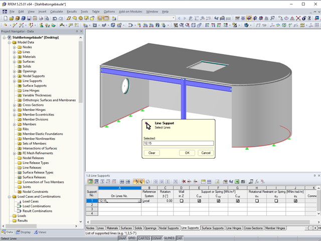
Line releases are special objects in RFEM 6 that allow structural decoupling of objects connected to a line. They are mostly used to decouple two surfaces that are not rigidly connected or transferring only compressive forces at the common boundary line. By defining a line release, a new line is generated at the same place which transfers only the locked degrees of freedom. This article will show the definition of line releases in a practical example.
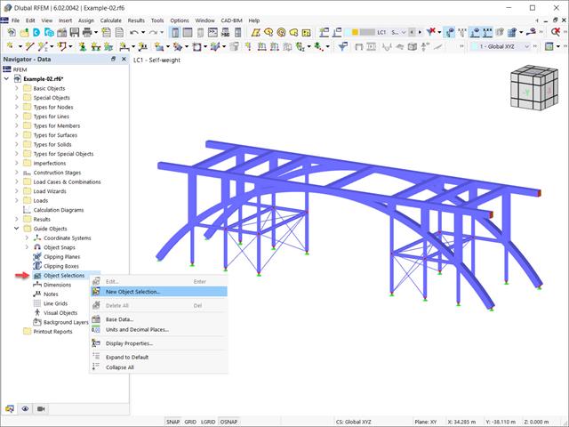
In the RFEM 6 and RSTAB 9 programs, it is possible to group objects based on different criteria. Hence, objects that meet the defined criteria can be selected and edited at the same time. This is possible with the “Object Selection” tool, which is comparable to “Special Selection” in RFEM 5. This article will show you how to group objects with “Object Selection" as a new guide object of RFEM 6 or RSTAB 9.

In RFEM 6 it is possible to save selected objects (as well as whole structures) as blocks and reuse them in other models. Three types of blocks can be distinguished: non-parameterized, parameterized, and dynamic blocks (via JavaScript). This article will focus on the first block type (non-parameterized).
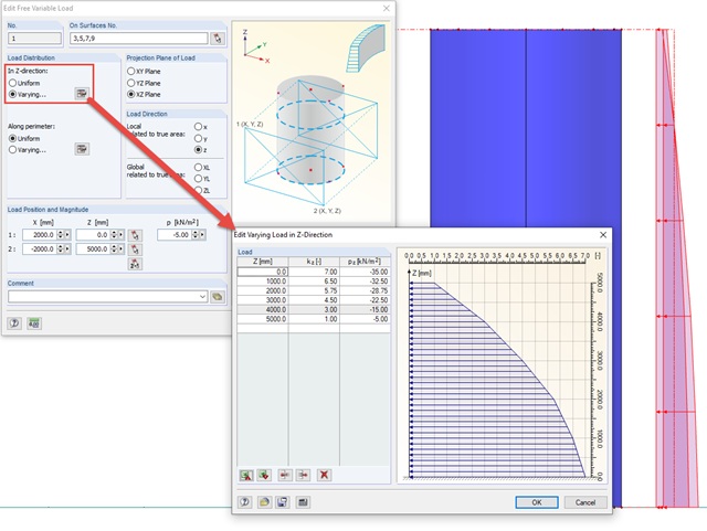
In order to apply loads that are variable in height and perimeter to rotationally symmetric objects, RFEM provides the free variable load.

If you want to consider guide objects in the overall view (F8 key or double-click on the mouse wheel) or, for example, in a particular direction of the views, you can enable this option in the settings of the particular guide objects (guidelines, background layers, line grids).
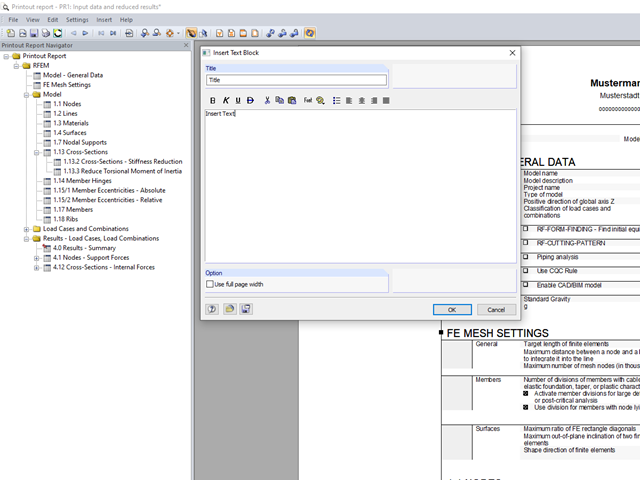
You can insert your own notes in the printout report. To do this, go to the printout report menu and click "Insert" → "Text Block."
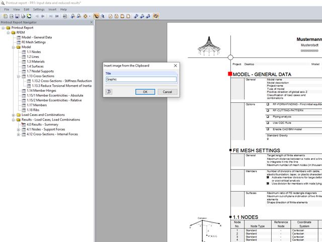
In RFEM and RSTAB, you can insert external images into the printout report.

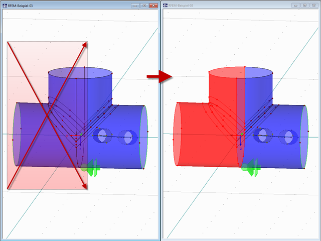
In RFEM, you can display the contact properties between two surfaces by means of contact solids. Among other things, you should ensure that both contact surfaces of a contact solid have the same integrated objects. Therefore, when modeling the contact surfaces, we recommend using the copy function in order to create the second contact surface.

RFEM and RSTAB save the input data, the FE mesh, the results, the printout reports, and the 3D gITF model preview, including all visual objects, in one file.

Inserting holes in surfaces is very easy due to the large selection of tools. In order to insert holes or drilling in solids, it is necessary to keep in mind that an opening at the beginning and the end of a continuous hole must be created, as well as a surface that separates the hole from the solids.
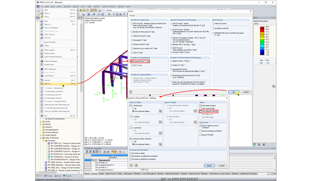
In RFEM and RSTAB, you can export the calculation results to an Excel document.
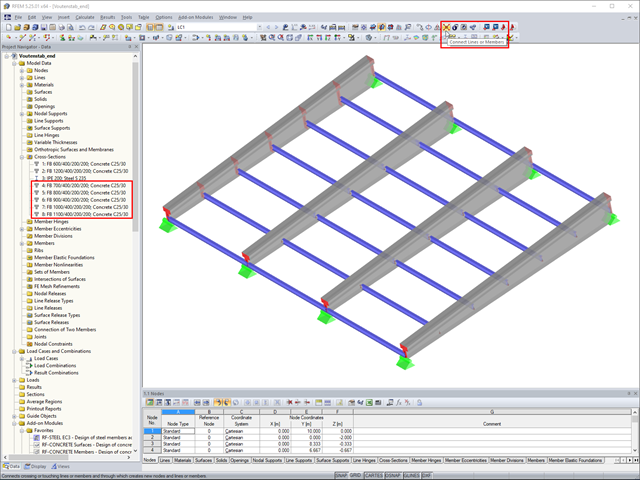
In RFEM, if you want to insert a tapered member with intermediate nodes into an existing model, the issue often arises how to determine the individual cross-section depths of the tapered members quickly. The "Connect Lines or Members" command comes in handy for this purpose.
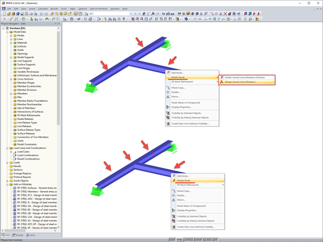
If you want to remove redundant nodes but keep connected objects, you can right-click the relevant node and select the "Delete Nodes" and "Merge Connected Members" options. In addition to members, you can also merge lines in RFEM.

The new "Result Beam" member type in RFEM 5 allows you to determine the load sums of individual floors easily. To do this, model a member in the relevant floor or in all floors, then specify the relevant walls as inclusive objects in the parameters of the result beam. RFEM then integrates the surface internal forces into member internal forces.
In the tables of RFEM 5 and RSTAB 8, you can select the list of objects graphically by using the mouse.

In RFEM, surfaces are automatically connected if they have common boundary lines. If the definition line of a surface is lying in another surface, the line is automatically integrated into the surface, provided that it is a planar surface. For quadrangle surfaces, however, automatic object detection would be relatively time-consuming. For this reason, the corresponding function is deactivated. The integrated objects must be specified manually.
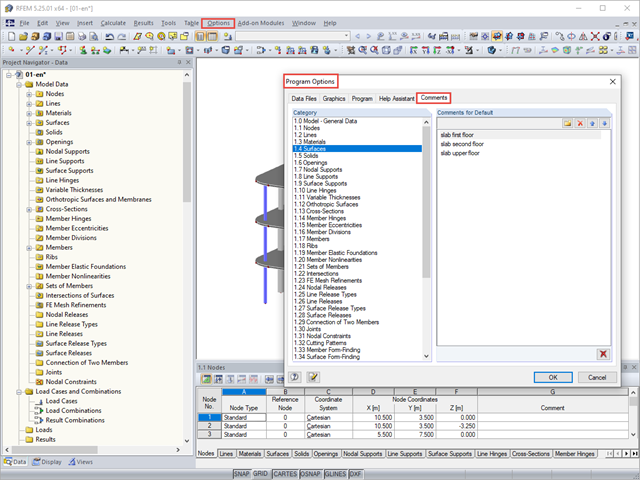
You can assign comments to each element in RFEM and RSTAB (structure element, load element, and so on). This can help to improve the overview and documentation of structures, as the comments appear in the printout report and, for example, certain objects can be filtered and displayed using the "Select Special" function.
Model and load objects can be defined graphically or in tables, or they can be created using parameters (see the manual). With this parameterized input, you can also access the cells of certain tables of the program. In this way, it is possible to link a load parameter with a model data parameter, for example. The reference is created by the $ sign.
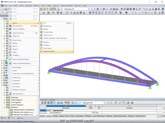
Sometimes it is necessary to add related objects, such as nodes and lines of a surface, to the selection in order to edit parts of the model.
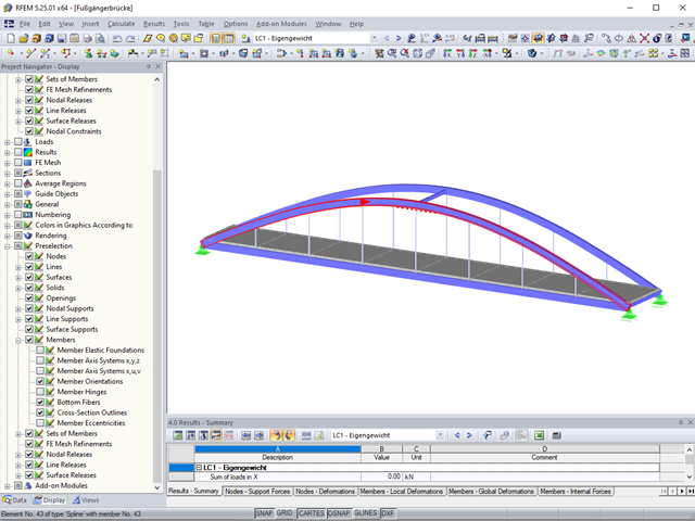
The preselection allows you to localize the relevant objects before clicking them.
If you draw a window with your mouse from left to right, all completely included objects are selected.

The shear force resistance VRd,c without computational shear force reinforcement according to 6.2.2 of EN 1992-1-1 [1] or 10.3.3 of DIN 1045-1 [2] is calculated depending on the longitudinal reinforcement ratio. If the required longitudinal reinforcement from the bending design is used for the calculation of VRd,c, this leads to an underestimation of the shear force resistance without shear reinforcement in the vicinity of the hinged end supports. In contrast to the shear force, the required bending reinforcement decreases in the direction of the support. Furthermore, the actually inserted longitudinal reinforcement usually deviates significantly from the required bending reinforcement in the end support area (for example, in the case of non-staggered beam reinforcement).
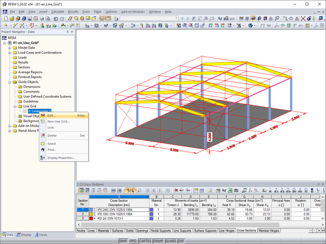
As a quick tool for changing the structure geometry, the "Line Grid" option is available in "Project Navigator – Data" under "Guide Objects".
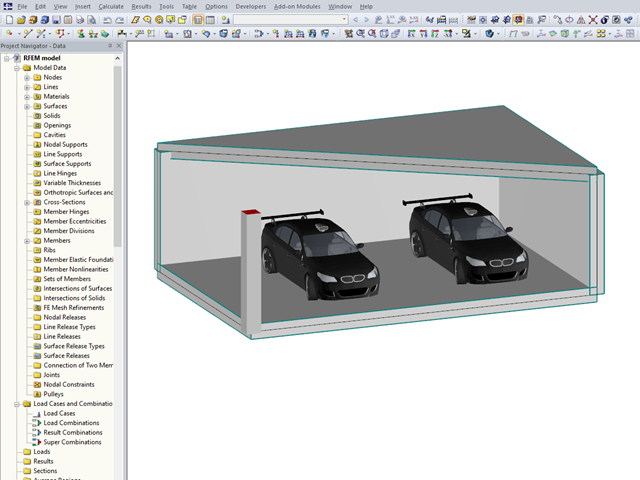
In RFEM 5 and RSTAB 8, you can add visual objects to the model in order to make a convincing impression on your client when presenting the structural model. These objects allow both laypersons and engineers to better understand the dimensions of the system.
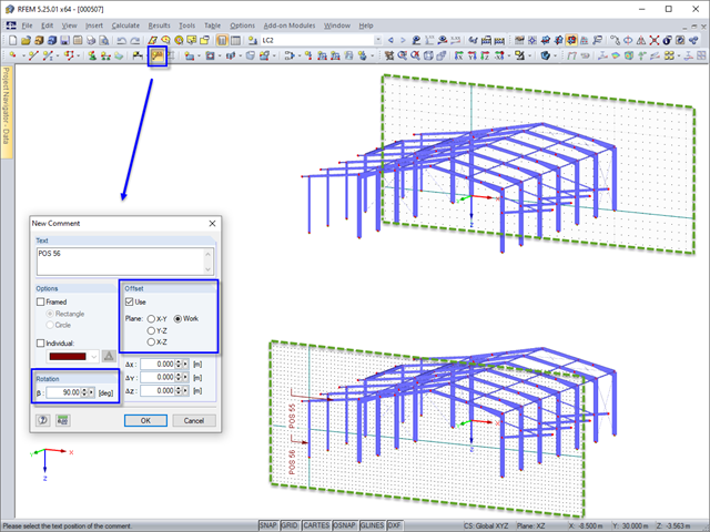
In RFEM and RSTAB, you can add a comment to model objects in the graphic. When inserting a comment, the origin of the current work plane automatically jumps temporarily to the same plane in which the comment is placed. This prevents comments from being accidentally placed very far from the object.
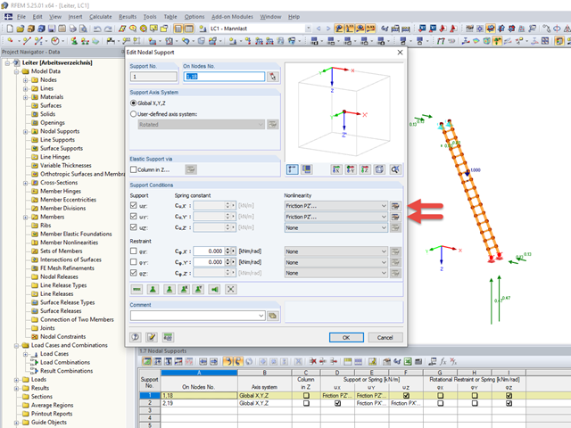
Friction plays an important role in practice. Without friction, the brakes of cars would be useless, objects on inclined planes would just slide away, and prestressed bolt connections would be impossible.
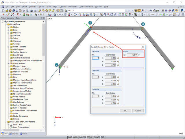
To determine the distance between two nodes or the angle between two objects without using the dimensioning function, you can simply use the "Measure" option on the "Tools" menu. Here, you can also choose between various measure functions.

In RFEM and RSTAB, you can use many interfaces to simplify the modeling of your structure. From background layers, to the import of IFC objects that can be converted into members or surfaces, to the import of the entire structural system from Revit or Tekla. Regardless of the performance of the selected interface, further utilization also depends on the accuracy of the imported data.